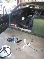
Pile of tools.
It never ceases to amaze me how many tools I have to drag out for the "Simple" jobs.
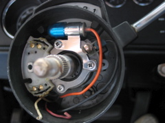
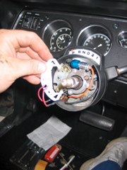
Here's what it looks like, all cleaned up, ready for the new top portion of the switch to be installed. I used Maguire's Clear Plastic Cleaner and Polish, and the Dremel-Mounted Q-Tip to clean the blue plastic lens.
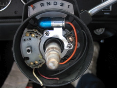
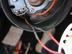
Apply a light coating of grease on the lower portion of the switch. Don't drown it in the stuff, a light coating will do. Pay particular attention to get it on the lobes that the cam will ride on for the upper part of the switch.
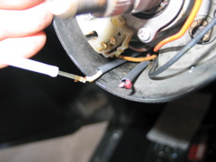
Slide some heat-shrink tubing onto the switch wires, and hit them with some flux to prep them for soldering.
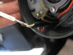
Why use flux when the solder has flux in it? The additional flux will activate before the flux in the core of the solder melts. It will strip oxidization from the 35 year old wires more effectively than cleaning with contact cleaner, or alchohol. For solder to stick, and form an intermetallic bond, the wires MUST be clean.
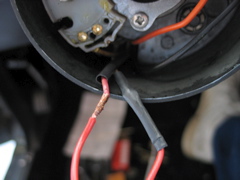
One down, one to go...Make sure you solder the wires from the new switch onto the correct wires. You don't want to have to singal left to make a right turn!
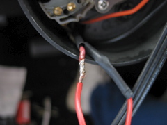
Soldered...
Tubing shrunk down to size. The tubing is a must. Don't use black electrical tape....it won't last.
Slide the new top portion of the switch carefully onto the shaft.
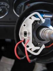
Route the wires as they were before, and put the screw back in. You'll have to play with how tight to make the screw...too tight, and you won't be able to turn the blinkers on! Reconnect your battery, and test for functionality before reassembling the wheel.